Define relationships in data models
You can add relationships between tables in a data model to enable business users to work with related data without performing ad hoc joins.
A relationship defines the join logic for Sigma to use to join the tables. After you define a relationship between two tables, the columns from both tables are available to the source table for analysis and exploration as needed. When a user analyzes the source table in a workbook and adds a related column, Sigma performs the join.
Relationships can help reduce unnecessary joins, which can improve performance and reduce cost. With a relationship, a join is only performed when a related column is added to a workbook element. If you use a join instead, the join is performed in the underlying SQL every time.
Sigma does not automatically create relationships between tables from a connected data source. Even if the tables have primary and foreign keys defined, you must create relationships between the tables in a data model to make the related columns available to downstream elements.
Relationships between elements are directional. Consider how your data is related when defining a relationship.
Guidance for modeling relationships
Relationships between data model tables only support many-to-one or one-to-one joins. When you define a relationship between tables in a data model, use the most-granular data table as the source element and add a relationship to one or more less-granular tables as target elements. Each row in the source table must have only one possible result in the target table, otherwise unintentional fanouts or wrong results can be introduced to workbooks that use the related column.
For example, if you use a star schema, use your fact table (for example, EVENTS) as the source element, and add a relationship with each dimension table (for example, USER, or EVENT_TYPE) as the target element.
For more details, see Relationships: what they are and how to use them in Sigma Community.
Add a relationship between two data model tables
Define a relationship to make additional columns available from a data model element.
You can only define relationships between elements on the same connection. All related elements must be in the same data model.
-
Open the data model for editing.
-
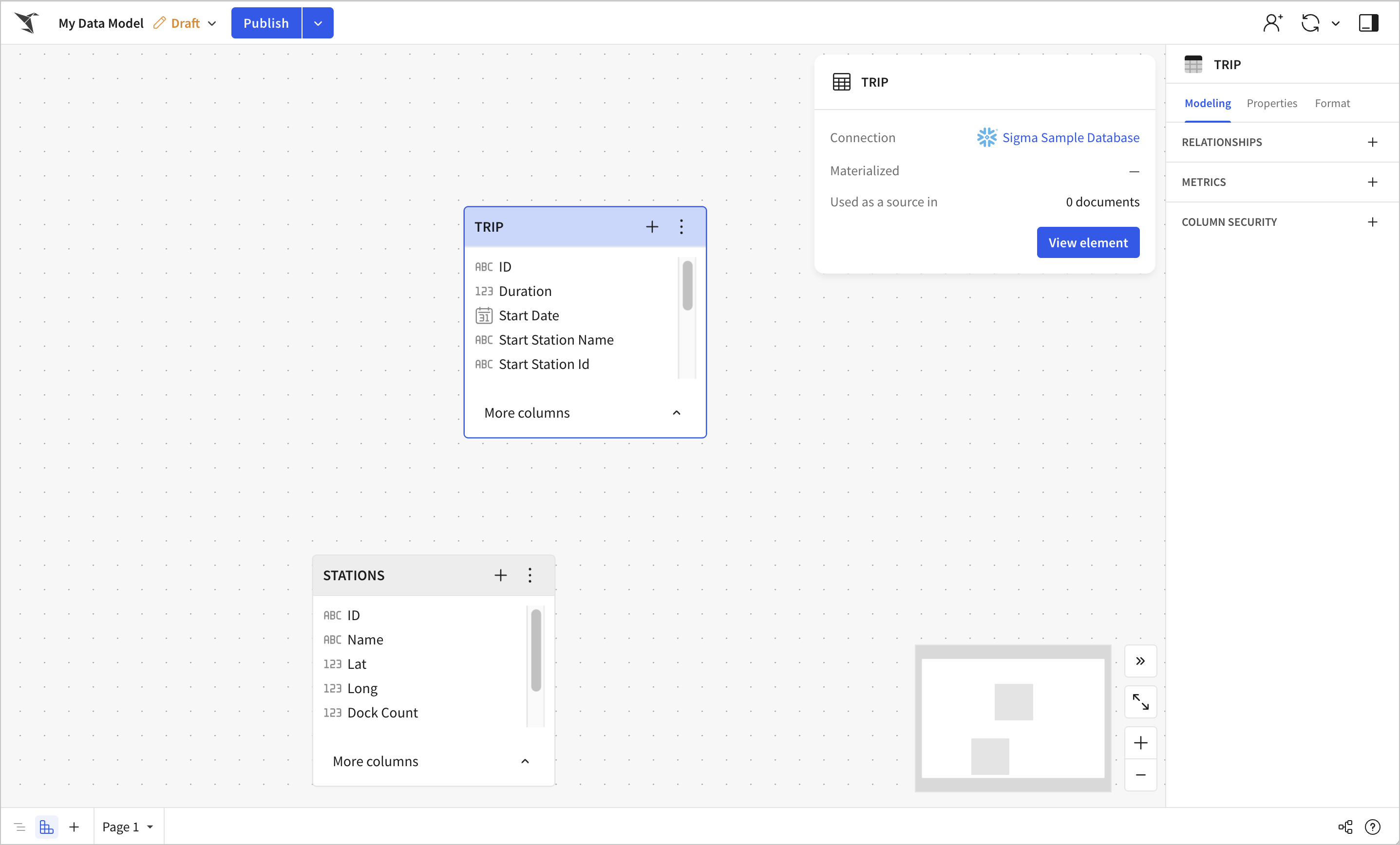
Select Data model ERD (
 ) to open the entity relationship diagram (ERD) view.
 -
In the Data model ERD view, select the source element for the relationship on the canvas.
-
In the editor panel, select the Modeling tab. In the Relationships section, select + (Add relationship).
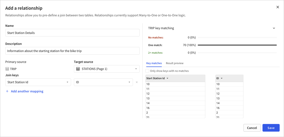
The Add a relationship modal opens.
-
(Optional) Name the relationship. By default, the relationship name uses the target element title.
-
(Optional) Add a description for the relationship.
-
For Target source, select an element in the data model to add as a target of the relationship. Adding an element as a target makes its columns available from the source element.
The target source can be an element disabled as a source. When the target source is disabled, the only way for downstream users to work with columns in that element is through this relationship.
-
For Join keys, select the columns from the source element and the target element to use as the join keys in the relationship.
-
(Optional) Click + Add another mapping to add more column mappings.
-
(Optional) Review the key matching details for the source and target elements to validate that your relationship is set up on the correct keys. Select Result preview to confirm the output of the relationship looks as expected.
-
Click Save.
-
To make the relationship available to downstream users, publish the data model.
For details about using related columns in a workbook, see Use related columns in a workbook.
Example relationship
For example, if you want to make the BIKES data in the Sigma Sample Database easier to analyze in a workbook, you can model and define a relationship as follows:
-
In your data model, using the Sigma Sample Database EXAMPLES.BIKES schema as a data source, add the TRIP table and the STATIONS table as two data elements.
The TRIP table provides details about bike trips taken on rental bikes. There is one row for every bike trip, so there are many total rows for each station.
The STATIONS table provides details about the location of each bike docking station. There is one row for each station.
-
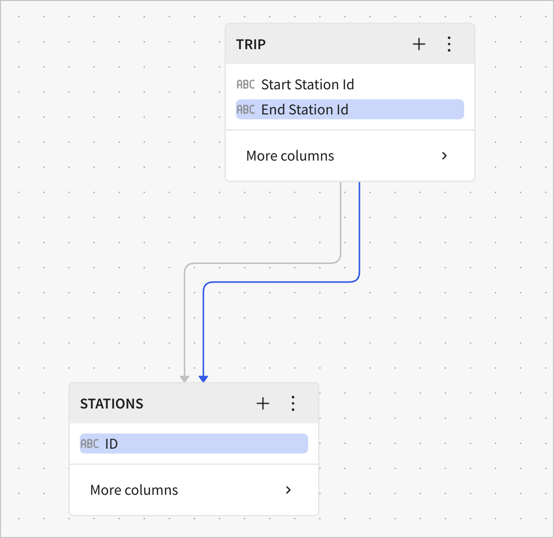
To create a relationship between the two tables, start from the TRIP table, using the STATIONS table as the target element. Creating a relationship in this direction defines the logic for a many-to-one join:
-
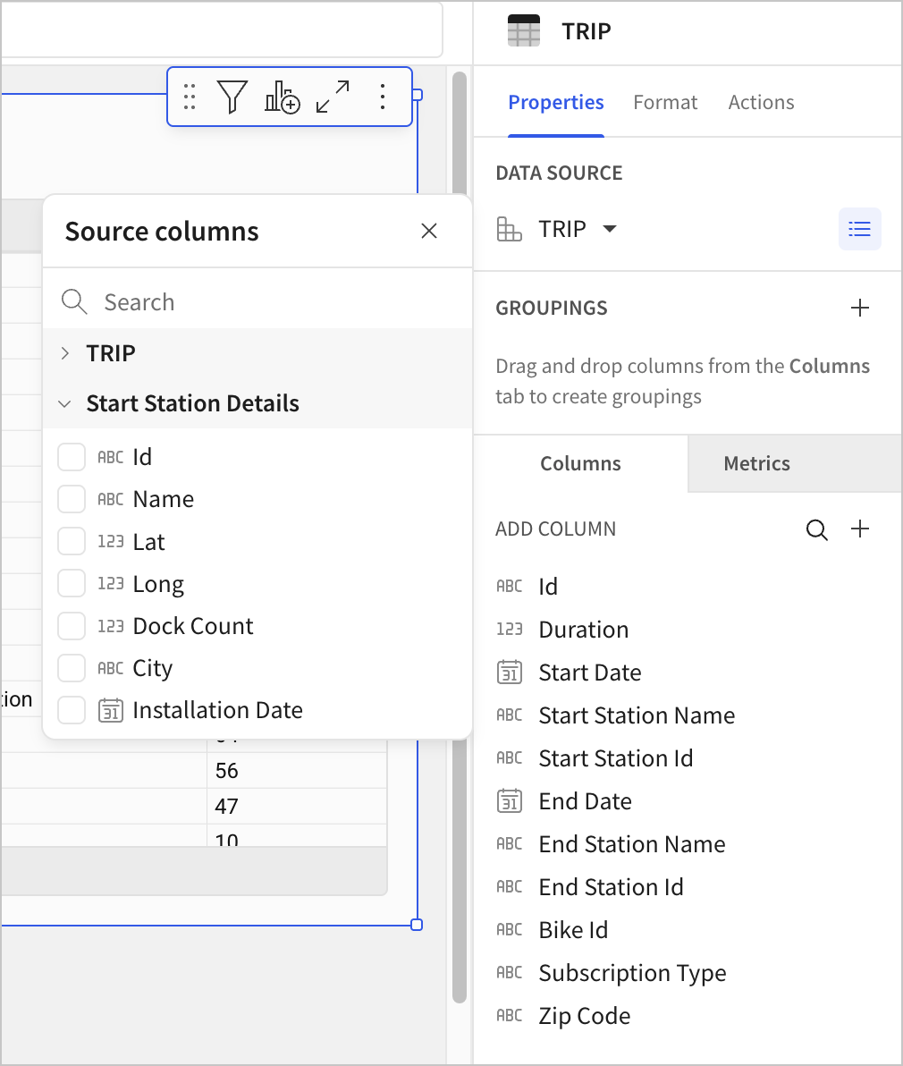
Then, after publishing the data model, business analysts can work with the TRIP table from the data model, easily adding related columns from the STATIONS table. Sigma performs a join based on the logic defined in the relationship, and the join is only executed when the related columns are added to the workbook:
Review existing relationships for data model elements
You can use the entity relationship diagram (ERD) for your data model to review the relationships between data model elements.
-
Identify directional relationships with the arrows connecting elements. Each relationship has a distinct arrow.
-
Select an arrow to highlight the relationship and the relevant keys in the source and target elements.
-
Identify which relationships are set up for which columns of the reusable elements.